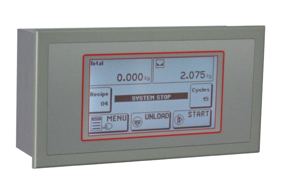
TOUCH SCREEN INDICATOR
LCD 5.2" graphic touch screen, high-contrast monochrome. Double channel input for load cells, incremental encoder input, dual analog outlet and additional analog input. Equipped with 6 digital inputs and 6 digital outputs, expandable with external modules.
On-board communication interfaces: RS232, RS485, USB, Ethernet, Modbus and Profibus DP. Optional USB Host port, for USB flash drives for data recording, uploading files and customizations.
![]() Click to enlarge image
Click to enlarge image

| Power supply | 24 V cc ± 15 % | |
| Max power consumption | 10 W | |
| Installation Category | Cat. II | |
| Operating temperature | -10 / +50 °C (14 / 122 °F) Humidity Maximum 85% non-condensing | |
| Storage temperature | -20 / +60°C (-4 / +140°F) | |
| Display | LCD 5.2 | |
| Display brightness | Backlight White LEDs, adjustable intensity | |
| Touch screen | Resistive 4 wires, suitable for use with gloves, buzzer | |
| Drilling template | 187 x 97 mm / 7.36 x 3.82 in (l x h) | |
| Overall dimensions | 196 x 105 mm / 7.72 x 4.13 in (l x h) | |
| Mounting | Recessed in front panel | |
| Protection level | IP 65 | |
| Connections | Removable screw terminal block 5.08 / 7.5 mm pitch USB standard connectors ( Host / Device ) RJ45 Ethernet standard connector | |
| Load cell input features | 2 input channels for load cells. Acquisition alternative or simultaneous at reduced frequency | |
| Power supply load cells | 5 V dc / 120 mA (maximum 8 cells with 350 Ω in parallel) protected against short-circuit | |
| Input sensitivity | 0.02 µV min | |
| Linearity | < 0.01% full scale | |
| Temperature deviation | <0,0003% of full scale/°C | |
| Internal resolution | 24 bit | |
| Weight resolution | Up to 600.000 scale intervals on scale capacity | |
| Measuring range | -7.8 mV/V - +7.8 mV/V | |
| Weight acquisition frequency | 12.5 Hz - 250 Hz | |
| Digital filter | 0.2 Hz - 50 Hz | |
| Communication ports | 3 independent communication ports (not switched) | |
| Max. cable length | 15 m (Rs232), 1000 m (Rs485) | |
| Serial protocols | TCP/IP, UDP, ARP, ICMP, ModBus/TCP | |
| Baud rate | Da 1200 a 115200 bit/sec | |
| Options | USB flash drive interface with FAT16 / FAT32 file system management | |
| Micro-controller | RISC 32 bit, 44 MHz | |
| Program code memory | Flash 256K Bytes, on-board upgradable (Rs232, USB) | |
| Data memory | 1088 KBytes standards, expandable up to 2113 KBytes | |
| Calendar clock | Integrated w/rechargeable battery | |
| Type | Top Terminal block pitch 5.08 mm |
| Length | ND |
| 1 | RS232 Tx COM2 |
| 2 | RS232 Rx COM2 |
| 3 | GND |
| 4 | RS232 Tx PRINT |
| 5 | RS232 CTS |
| 6 | TX+/RX+ RS485 COM2 |
| 7 | TX-/RX- RS485 COM2 |
| 8 | TX+ RS422 COM1 |
| 9 | TX- RS422 COM1 |
| 10 | RX+ RS422 COM1 |
| 11 | RX- RS422 COM1 |
| 12 | Out analog. 1 mA |
| 13 | Out analog. 1 V |
| 14 | Out analog 1 GND |
| 15 | Out analog. 2 mA |
| 16 | Out analog. 2 V |
| 17 | Out analog 2 GND |
| 18 | In analog. Volt |
| 19 | In analog. GND |
| 20 | Encoder power |
| 21 | Encoder GND |
| 22 | Encoder Phase A |
| 23 | Encoder Phase B |
| Type | Bottom Terminal block pitch 5.08 mm |
| Length | ND |
| 1 | - Exc. Load cell |
| 2 | + Exc. Load cell |
| 3 | + Ref. Load cell |
| 4 | - Ref. Load cell |
| 5 | Load cell 1, signal - |
| 6 | Load cell 1, signal + |
| 7 | Load cell 2, signal + |
| 8 | Load Cell 2, signal - |
| 9 | Input 1 |
| 10 | Input 2 |
| 11 | Input 3 |
| 12 | Input 4 |
| 13 | Input 5 |
| 14 | Input 6 |
| 15 | Common input |
| 16 | Output 1 |
| 17 | Output 2 |
| 18 | Output 3 |
| 19 | Output 4 |
| 20 | Output 5 |
| 21 | Output 6 |
| 22 | Common output |
| Type | Bottom Terminal block pitch 7.5 mm |
| Length | ND |
| 23 | Power supply 24 Vdc |
| 24 | GND |
General precautions to be followed in the installation and assembly of load cells: